 |
| Click to enlarge |
This is also another useful project for anyone working in electronics.
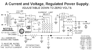
Both Current and Voltage Regulation is Extremely Important to Help Prevent Damage to Circuit, Especially Experimental Circuits.
This circuit used a Rotary Switch to select Various Current ranges as a Potentiometer is not very practical for the lower resistance/High Current Ranges.
But if you wish to change it to a pot, you can try it. It is practical to use a pot on the lower current ranges so the lowest switch range could be a pot with a small series resistor. Allowing for adjustment from say “10 mA to 500 mA”. Than use fixed resistors on the higher current ranges.
This circuit will give you a Very Simple, but a quite versatile Voltage and current regulated Supply. And Down to “Zero Volts” out is a Nice Feature.
You are recommended to making two of these. This will allow for “Plus and Minus” supply voltages, when needed. They can Also be Paralleled or placed in Series for Higher Currents or Higher Voltages, As is Sometimes Needed.
The Output is reasonably short circuit protected if suitable heat sinks are used and this supply should go down to Zero or very near Zero Volts.
Output Voltage and current depends somewhat on the transformer used, as well as which Regulator used. You have a choice of an LM317 for 1.5 amps Max, or an LM350 to give about 3 amps Max.
All of these LM317 or LM350 chips in this circuit REQUIRE SUITABLE HEAT SINKS. As they would also in any other high current power supply.
Source : telus.net/chemelec
Tags:
Power supply