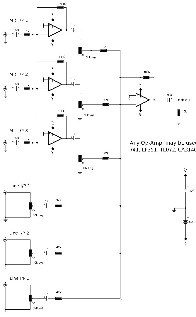
Schematic circuit diagram for 6 Input Mixer
This schematic circuit diagram shows the mixer circuit that has 3 line inputs and 3 mic inputs.
- The final summing amplifier has a gain of 2 or 6dB
- The Input line level should be around 200mV RMS.
- The mic inputs are suitable for low impedance 200-1000R dynamic microphones.
- An ECM or condenser mic can also be used, but must have bias applied via a series resistor.
- The mic inputs are amplified about 100 times or by 40dB, the total gain with the mixer is 46dB.
- The mic input is designed for microphones with outputs of about 2mV RMS at 1 meter. Most microphones meet this standard.
Tags:
Audio Circuit