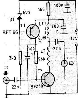
A very simple antenna amplifier electronic circuit project can be designed using this circuit diagram .
This antenna amplifier electronic circuit can be used for a frequency range between 1 and 300MHz .
This circuit antenna amplifier can be used for high frequency and VHF band ( for radio and TV) and will provide a 22 dB gain .
This antenna amplifier electronic project has a very low noise , under 1.6dB .
This VHF, FM amplifier circuit is constructed based on the BFT66 transistor connected in common emitter connection.
L1 coil has a 6uH value , but can be used any coil for high frequency ( with a value between 5.6 to 6.8 u H) .
L2 coil is an air core type coil and it has 5-6 turns (10mm long and 5 mm diameter) . For L2 coil can be used a 0.25 mm Cuem wire .
The pcb of this circuit must be placed near the antenna , in a small metallic box . This VHF antenna circuit must be powered from a 12 volts DC power supply circuit , you can use a 12 volt battery , because the current consumption of this circuit is very low under 10mA.
You can replace T1 transistor wit some other UIF similar transistor type which have a very low noise factor.
